13 Feb 2024
Hannah van Velzen shares the various techniques for this examination she has encountered in her career.
Hannah van Velzen
Job Title
It is no understatement that intra-oral radiography is one of the fundamentals of dentistry.
Its function is not dissimilar to that of an otoscope or ophthalmoscope, in that it allows the veterinary surgeon to see and evaluate important anatomical structures that would otherwise not be visible. Such is its importance that without full-mouth dental radiography, we would miss clinically important findings in 27.8% of dogs and 41.7% of cats1,2 with otherwise normal-looking mouths.
It is, therefore, surprising that, despite these figures being published more than 25 years ago, dental radiography is still not a part of the standard practice set-up.
Besides treatment planning, dental radiography is also a way of ensuring treatment control and minimising complications. One study found 82.4% of dogs and 92.8% of cats had radiographic evidence of retained tooth roots after carnassial extraction, despite clinicians having been confident they had performed the procedure successfully3.
With around 55% of retained tooth roots having been shown to have radiographic or visual evidence of inflammation3,4, the importance of obtaining post-extraction radiographs is undeniable.
In addition, dental radiographs can establish a baseline for ongoing monitoring of oral disease and can be an important visual aid for discussion of treatment options with owners.
Luckily, the amount of clinics investing in this essential piece of equipment is on the rise, but with that follows the new challenge of becoming familiar with its use. No one will deny the learning curve for getting even diagnostically adequate radiographs is steep, but with regular practice and a basic set of positions, you will quickly find taking them to be a more rewarding experience.
Both computed radiograph (CR) and direct digital radiograph (DR) systems are available, with varying opinions between clinicians on which is “best”. In truth, both systems have pros and cons, and any individual clinician should practise with and use the system they are most comfortable with (Table 1).
| Table 1. Computed radiograph (CR) versus direct digital radiograph (DR) sensors | |
|---|---|
| CR | DR |
|
|
More important for ease of use is installing an x-ray generator with a sufficient range of motion, to allow for the various necessary positioning angles to be used. Too often, staff are expected to take diagnostic images with a conventional fixed generator, requiring coordinated movement of the patient from the dental surgery table to the x-ray room and repeated changes in patient head positioning.
Wall-mounted generators, generators on mobile floor stands and even handheld units on the other hand allow any angle to be achieved with minimal changes in patient position; therefore, speeding up and decreasing the difficulty experienced with dental radiography. When taking radiographs with a size 2 plate, the x-ray generator should be positioned as close to the patient as possible. However, when larger-sized plates are used, the x-ray generator should be positioned further away from the patient to allow for exposure of the full plate.
In this section, the author will discuss the three most commonly used techniques, which when used together, allow for the creation of a full-mouth set of dental radiographs in cats and dogs (Table 2).
| Table 2. Projections used for full-mouth dental radiography in dogs and cats | ||
|---|---|---|
| Projection | Dogs | Cats |
| Parallel projection | Mandibular molar teeth Distal mandibular premolar teeth |
Mandibular premolar teeth and molar tooth |
| Bisecting angle | Maxillary/mandibular premolar teeth (45°) Maxillary/mandibular incisor and canine teeth (less than 45°) |
Maxillary premolar teeth (30°) Mandibular premolar teeth (45°) Maxillary/mandibular incisor and canine teeth (less than 45°) |
| Tube shift | Maxillary fourth premolar | Maxillary fourth premolar |
| Extra-oral transorbital | Maxillary molar teeth | – |
| Extra-oral near parallel | – | Maxillary premolar and molar teeth |
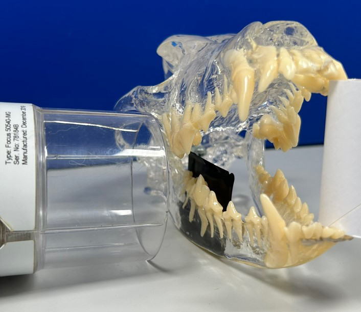
Arguably the easiest position to start with, the parallel projection gives the most accurate representation of tooth size and is, therefore, the most favourable version of an intra-oral radiograph. Sadly, its use is limited by the ability to place the sensor/plate parallel to the tooth, which is only possible on the mandibles and in the area distal to the symphysis.
To get this projection, the plate is placed between the tongue and dental arcade to be imaged. The x-ray beam is then pointed directly towards the sensor/plate surface (Figure 1).
In comparison to the parallel projection, the bisecting angle is one of the most difficult techniques to fully understand, but also the most widely used technique for intra-oral radiography.
What it attempts to achieve is to angle the x-ray generator in such a way that the image of the tooth projected on to the sensor/plate is an accurate representation in terms of its height and width.
An easier way to understand this is to consider the image of the tooth on the sensor/plate as a “shadow” of the tooth, with the x-ray generator functioning as a “light” source. If the generator is “too high”, the shadow will be too short, while if the generator is “too low”, the shadow will be too long.
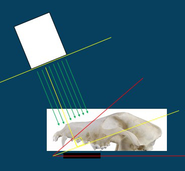
If the correct angle is achieved, the shadow will be exactly the same height and width as the tooth.
This “perfect angle” is the bisecting angle. It is called this because it is exactly half of the angle between the plate and the axis of the tooth (that is, sections the angle in two). The x-ray generator should be positioned perpendicular to the bisecting angle (Figure 2).
Theoretically, the bisecting angle should be suitable for use in all teeth, as it can be altered to fit the exact angle of the long axis of each individual tooth. However, it is not commonly used for the distal mandibular teeth, as the soft tissues in this area limit such caudal placement of the sensor/plate.
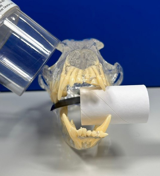
For the premolars and molars that can be imaged, the angle is approximately 45°, whereas for the incisors and canines, the generator position should be slightly steeper to compensate for the root curvature making the overall “tooth angle” less vertical (and, therefore, smaller; Figures 3 and 4).
An altered bisecting angle should be used for maxillary premolar teeth in cats due to the position of the zygomatic arch. As typical for teeth in this region, the roots are very vertical, and the bisecting angle would, therefore, normally be approximately 45°. However, taking the image with this angle usually results in overlap between the zygomatic arch and apical root region, obscuring accurate viewing.
Use of a slightly larger (lower) angle results in a somewhat elongated image, but avoids this overlap. The resulting angle is approximately 30° (Figure 5).
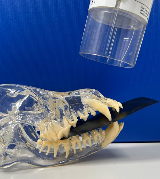
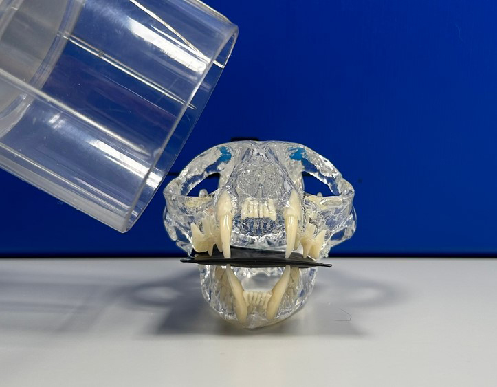
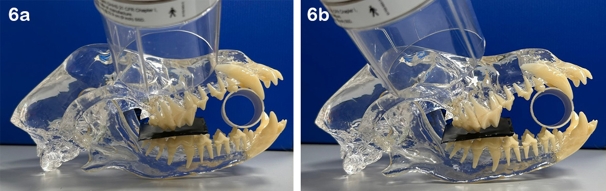
The maxillary fourth premolar tooth is a three-rooted tooth and, as a result of its shape, 2D imaging will inevitably result in overlap of the mesial roots. A tube shift is used to remedy this.
For this projection, the plate and patient remain in the same position. The vertical angle of the x-ray generator also remains the same, but the tube is shifted to point from distal to mesial. Shifting the tube like this will result in an angled and slightly elongated projection, in which the mesial roots are now visible as individual roots side by side (Figure 6).
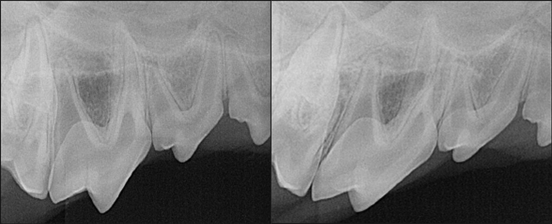
To determine which root is which, remember the SLOB rule: “same lingual, other buccal”.
In this case, the tube has been shifted to project from more distally; therefore, the more distal root on the image (“same” direction as the tube shift) is the lingual/palatal root. The more mesial root on the image (“other” direction from the tube shift) is the buccal root (Figure 7).
Tube shifts can also be used to determine if lesions noted on radiographs are associated with the tooth or are separate from it. If a tube shift is performed and the lesion remains in the same relationship to the tooth as the original radiograph, it is associated with the tooth. If it moves independent from the tooth, then it is separate.
This technique is particularly useful to distinguish periapical pathology from the mental foramen in the rostral mandible.
The projections previously described are enough to start a clinician off with a standard set of full-mouth radiographs. As you become more familiar with its use, additional projections can be added to obtain more information.
One thing to be aware of with the extra-oral projections described in this section is that on the image acquired, the teeth will be mirrored from the way they appear on intra-oral projections; therefore, these projections should be clearly labelled as such to prevent confusion between left and right at the time of interpretation.
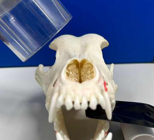
As three-rooted teeth, the maxillary molar teeth suffer from similar issues with overlapping roots as the maxillary fourth premolar tooth.
Detailed examination of the periapical regions and the furcation between the buccal roots can be achieved by use of the transorbital projection, which was recently published5.
This extra-oral projection can practically be thought of as a reverse of the standard bisecting angle used to image these teeth. The sensor/plate is positioned more laterally, in such a way that it partially protrudes extra-orally.
The x-ray generator is then angled to point from the contralateral side (rather than the ipsilateral), through the orbit, to project the tooth on to the extra-oral portion of the sensor/plate.
It has been proposed that this projection should be added on to the standard set of full-mouth dental radiographs, which is certainly achievable after some practice (Figure 8).
An alternative way of circumventing the zygomatic arch in cats is to use an extra-oral near parallel projection. Although it is technically more challenging and does require some practice, it certainly allows for a less obscured view of the maxillary premolar/molar region, and should ideally always be performed to fully rule out retained roots and tooth resorption in cats.
For this projection, the patient is placed in a lateral with the mouth propped open (avoid the use of spring-loaded gags). The sensor/plate is positioned between the patient and the table surface. The x-ray generator positioning is started straight above the patient, angled perpendicular to the table surface, and then tilted approximately 20° to point from more ventral to dorsal (Figure 9).
Full-mouth dental radiography is an essential tool for veterinary dentists and requires only a few different projections.
Although some of the techniques may be challenging at first glance, a simplified standard approach such as the ones described in this article can be more than adequate for achieving diagnostic radiographs.
With further practice, clinicians can then branch out to additional extra-oral and custom projections to truly make the most of this imaging modality.